|
Arduino Shutter Tester
If you have old film cameras, you might
wonder how accurate they are. There are many areas of wear and tear but the most obvious are
the shutter and the exposure meter. I recently took a few minutes to assemble a simple device
to address the former. Here are my notes from the build, along
with train of thought, test data and conclusions. It's definitely not "done" but given the
nature of the project, I reached a good stopping point and saw no need to continue any
further.
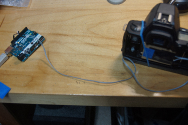
Description & Goal - a simple device,
not a standalone/turnkey device (requires computer connectivity for I/O).
Packaging is little more than a sensor puck and cable. The user
provides an arduino with software, USB cable to computer for power
and communication, the computer, and light source.
No effort is made to keep this combination assembled on a permanant basis; it will
be assembled when needed. This lowers overall cost by removing the need for an output
display and dedicated input device (use computer instead). As for the project
itself, this is a one-day project and I don't plan on doing more than
I have to :)
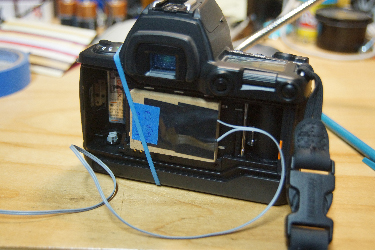
The concept couldn't be simpler.
Connect a phototransistor as a sensor to an arduino. Place the sensor on the film
plane, shine a light from the front of the camera
and measure the duration that the sensor
is exposed to the light when the shutter is triggered.
I considered two options on phototransistor usage - put one in the center of the
field or use more than one and be able to track shutter movement
(horizontal, vertical, radial).
Another consideration
regarding the number of phototransistors - it's important to acquire all
phototransistor states in a single read. A single byte
read from a port can acquire the state of up to 8 phototransistors but
arduino 8 bit ports
are often shared across multiple functions so the net number of bits
read in parallel maybe less than 8. After some testing, it made
the most sense to just go with a single phototransistor at the center.
There's also the choice of which
arduino to use. The generic model is the Uno. It runs on an 8MHz clock. A faster
Mega2560 runs on a 16MHz clock. For even more throughput, faster variant can be used - but
are they necessary? To capture elapsed time, the micros() function will be used and
on the Uno, that function has a time resolution of 8 microseconds. On the Mega2560 the
resolution is 4 microseconds. This gives us more than enough timing accuracy and about 70 minutes of elapsed runtime before the
time counter wraps. Ultimately which board to use wasn't an issue and I was
limited by other factors. Like all engineering problems, it all boils down to the
weakest link.
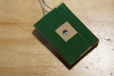
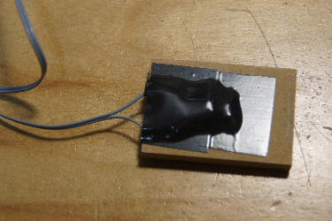
Let's get the sensor out of
the way. The phototransistor is Vishay TEPT5600. Why this one?
Because it's what I had. It comes
in a T1-3/4 housing which measures 5mm in diameter and 8.6mm tall. I drilled a hole
into the center of a piece of 1/4 inch hardboard. The head of the
phototransistor sticks out just a
bit so I added some felt padding - this also helps prevent abrassion to any areas
on the back of the camera during testing.
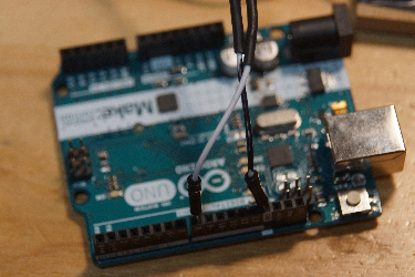
Two wires are connected to the phototransistor; it will
be used in a common emitter configuration. The emitter will go to ground while the
collector goes to the digital input on the arduino. A built-in pullup on the
GPIO pin will pull the signal to Vcc when there is no light. The pins used for
data collection will be pin 8 when used on the Uno and pin 53 when used on the
Mega2560 (this is bit 0 on port B). Ground can be found on pin 4.
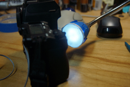
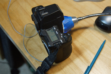
My first light source was
just a table lamp. I would aim the camera a the lamp to get a reading.
To make things easier to use, I later went with an LED gooseneck lamp
with wax paper as a diffuser.
Another decision to be made
involves actual data collection. There are several ways to perform the light
sensing.
The original plan was to use
a local buffer and read data in a tight loop. This would give the smallest
latency in-between reads but will require 2 passes - one pass to collect the data
and one pass to parse it to check its contents. The Mega2560 has 8KB of local RAM
while the Uno only has 2KB. By doing some profiling I can determine the time between
samples and avoid having to call micros() entirely. To make the buffer last longer
I can store just the light transisions (from on->off, off->on) but then I need to
store some additional information to give me timing details - either an actual
timestamp or the number of reads between recorded samples. But the biggest problem
with this sampling method is that any change in the underlying infrastruture such as the
compiler or IDE could change the timing profile and require me to recalibrate.
As it turns out
the arduino is fast enough; fast enough that I can sample in one pass and insert
all the other necessary logic during the acquisition.
I would use the micros() call for the
timing reference.
Earlier I mentioned reading data
as bytes directly from a port. This is important for performance. I don't read data
using the digitalRead() function as there is too much overhead built-in. I use
PINB instead and grab the entire byte from port B. See source code below.
Speaking of source code, here's
what the code does. It's pretty dumb and simple. Since the arduino operates in a loop
via the loop() function, I use each pass of the loop to capture one shutter release.
For each pass, the code waits for the sensor to register light. When it does, it
stores the timestamp by calling micros(). It then waits for the sensor to go
dark and stores that timestamp. The difference is calculated and data is sent to the
debug console for the user. The process repeats for the next shutter release.
That's pretty much it for the
actual testing jig. I did write other code that was used on the way to this
final version of the tester but this version proved to be both simpler and functional.
So how well
does this work? In actual testing, as shutter speeds go up
the tested shutter seem to be off by quite a bit. But is this the shutter that is
inaccurate or the tester? After a lot more testing (more than I had time for really)
I think I've reached
the limitations of the phototransistor in the simple circuit as used.
To make it more accurate
at higher shutter speeds,
the current simple and dumb input circuit would have to be more carefully designed
and the light source would need to be carefully controlled and calibrated.
I would need to avoid
optical saturation of the phototransistor, be mindful of the light color, control the pull-up
resistor to get better response time and lower the RC constant (note the need for a
settling time during the init of the code), and probably add a front-end buffer.
All of this is beyond the scope of this one day project. If anyone wants to contribute
a revamped front end design, I'll be happy to try it out ! :)

Here is a table
for two tested camera bodies. One is an old Pentax Spotmatic. The other is a more
modern Contax NX. This is just one run. I can tell you that on repeated runs,
speeds above 1/250 tend to diverge significantly from the desired value
and can vary quite a bit from run to run. Sometimes a good value creeps in but
they are more the exception than the rule.
| Speed | Spotmatic | NX |
|---|
| 1/4000 | N/A | 1/1063.83 |
| 1/2000 | N/A | 1/718.39 |
| 1/1000 | 1/1041.67 | 1/535.33 |
| 1/500 | 1/269.40 | 1/349.16 |
| 1/250 | 1/191.13 | 1/208.16 |
| 1/125 | 1/105.57 | 1/115.96 |
| 1/60 | 1/48.67 | 1/60.98 |
| 1/30 | 1/25.25 | 1/31.40 |
| 1/15 | 1/13.74 | 1/15.94 |
| 1/8 | 1/7.21 | 1/8.03 |
| 1/4 | 1/3.48 | 1/4.03 |
| 1/2 | 1/1.77 | 1/2.02 |
| 1 | 1.06357 sec | 1/1.01 |
| 2 | N/A | 1.97803 sec |
| 4 | N/A | 3.95511 sec |
| 8 | N/A | 7.90927 sec |
| 16 | N/A | 15.81760 sec |
| 32 | N/A | 31.63434 sec |
And now for the
source code.
/*
 * Shutter Tester
 * This tester is for a sensor assembly that contains just one phototransistor
 *
 * The code will
 * (1) use the serial debug output to show the calculated shuter speed
 * (2) use the serial debug output to show errors
 * (3) start when the sensor is dark
 * (4) wait until the sensor shows light
 * (5) stop when the sensor is dark again
 * Sensor input is the collector of the phototransistor and is wired to PortB<0>
 * On the Uno this is connector pin 8
 * On the Mega this is connector pin 53
 * We use different pins because we are reading the entire port (for speed) and not
 * reading the pin through the arduino library (too slow)
 */

#define INPUT_SETTLE_USEC 2000

void setup()
{
  char value;

  // for user I/O
  Serial.begin(115200);

  // enable pullup resistor
#if defined(ARDUINO_AVR_UNO)
  pinMode(8, INPUT_PULLUP);
#endif
#if defined(ARDUINO_AVR_MEGA2560)
  pinMode(53, INPUT_PULLUP);
#endif

  // Set up Port B. Bit<0> is input. Keep the rest as-is
  DDRB = DDRB & B11111110;

  // Wait some time to let the input settle from the phototransistor
  delayMicroseconds(INPUT_SETTLE_USEC);

  // sanity check. Make sure the sensor is dark. If not, it's an error
  value = PINB & 0x1;
  if (value == 0)
  {
    Serial.println("Sensor is not ready. Put sensor on film plane and make sure shutter is closed");
    Serial.println("Restart when ready");
    while(1);   // stop
  }
}

// One pass in loop() per shutter release
void loop()
{
  unsigned long startTime = 0;
  unsigned long endTime = 0;
  bool bDone = false;
  char newValue;
  unsigned long elapsedTime;
  float fTime;
  float fSpeed;

  Serial.println("Waiting for shutter to fire");

  // Now wait for the sensor to show light. That will be when the shutter is tripped.
  bDone = false;
  do
  {
    newValue = PINB & 0x1;
    if (newValue == 0)
    {
      startTime = micros();
      bDone = true;
    }
  } while(! bDone);

  // Now wait for the sensor to go dark again. That will be when the shutter closes
  bDone = false;
  do
  {
    newValue = PINB & 0x1;
    if (newValue == 1)
    {
      endTime = micros();
      bDone = true;
    }
  } while(! bDone);

  // Calculate the difference in start and end time. That's how long the shutter was open.
  Serial.println("Shutter fired");
  elapsedTime = endTime - startTime;
  fTime = float(elapsedTime) / 1000000.0;
  fSpeed = 1.0 / fTime;

  Serial.print("Shutter Speed = ");
  Serial.print(fTime, 5);
  if (fTime >= 1.0)
  {
    Serial.println(" sec");
  }
  else
  {
    Serial.print(" sec or 1/");
    Serial.println(fSpeed, 2);
  }
}
|